Adjustment for LPVR-DUO
By default low pass filtering is applied to LPMS-IG1 gyroscope output. This improves the quality of the signal for applications with slow rotations. In case of faster rotations e.g. in a motion simulator it is recommended to change the low-pass filter settings for the sensor to become more responsive. Please .
In this example, we are changing the low pass filter settings of the GyroI (high precision) gyroscope. Please follow the steps below to do this:
Save sensor settings file from sensor
Open IG1Control
Connect to LPMS-IG1
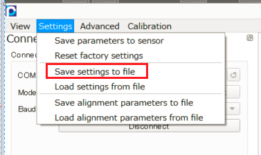
Go to menu bar → Settings → Save settings to file
In the file you saved, change G1F to 2500 as shown below:
...
Save file in the editor
...
Create a yaml file, eg. IG1_G1_LP2500.yaml, with the following content:
Code Block SETTINGS: ADVANCED: 1 G1F: 2500Open LpmsControl2 and connect to LPMS-IG1
Upload the created IG1_G1_LP2500.yaml settings to sensor:
menu bar → Settings → Load settings from file > Select IG1_G1_LP2500.yaml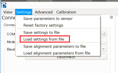
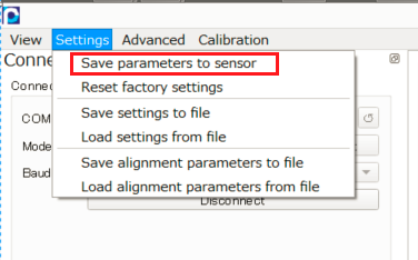
Save settings to sensor:
menu bar → Settings → Save parameters to sensor
...
Power cycle. The sensor should now respond faster to orientation changes.
You can save a copy of the settings to file and look for the value of G1F to confirm settings are successfully applied:
Generally Available Settings
...
In the settings file the following lines can be edited to change the filter settings for LPMS-IG1 gyroscope and accelerometer:
...
Possible accelerometer / gyroscope settings:
Accelerometer settings:
...
Key | Description | Available Values |
|---|---|---|
AR | Acc Range (g) | 2, 4 (default), 8, 16 |
AOR |
...
Acc output data |
...
rate |
...
(Hz) |
...
3, 7, 15, 31, 62, 100 (default), 125, 200, 250, 500, 1000 | |
AF |
...
Acc 3-dB bandwidth |
...
(Hz) |
...
5, 10 (default), 21, 45, 99, 218, 420 |
Gyroscope settings:
GR | Gyro range (dps) |
...
400 (default), 1000, 2000 |
...
G1OR | GyroI (high precision) |
...
output data rate (Hz) |
...
100, 200, 400, 800, 1600, 3200, 6400, 12800 (default) | |
G1F | GyroI ( |
...
high precision) low pass filter |
...
settings | value of G1F is calculated as: G1F = LpfOrder*1000 + LpfFrequency where:
|
G2OR |
...
GyroII ( |
...
high range) |
...
output data rate | 3, 7, 15, 31, 62, 100 (default), 125, 200, 250, 500, 1000 |
G2F | GyroII ( |
...
high range) 3-db bandwidth |
...
(Hz) |
...
5, 10 (default), 20, 41, 92, 176 |
IMPORTANT: Please make sure AOR and G2OR settings are the same. This is because the accelerometer and gyroscope II belongs to the same chip and share the same data output rate. In case of different values, G2OR value will be used to set the chip data output rate. Please note that the parameters will be erased and revert to default values if a factory reset is performed.
NOTE: These extended settings are usually not required for optimum LPVR-DUO performance.
Default settings:
| Code Block |
|---|
SETTINGS:
  ADVANCED: 1
  AR:  4
  AOR: 100
  AF:  10
  GR:   400
  G1OR: 12800
  G1F:  4010
  G2OR: 100
G2F: 10 |